Skip to content

Single Phase Sine Wave Inverter Equations

Onda sinusoidal - Traders Studio

What inductive loads will do to your inverter Ac waveform How a waveform is generated – trigonometry and single phase ac

Onda sinusoidal - Traders Studio

Gating signals and output waveform for pwm sine wave single phase Ac generation analysis : effective values, phase angle and frequency Sine sinusoidal onda investopedia sinewave traders gu10 220v flickering jiang

Single-phase vs. three-phase: the difference explained!

Sine convert equationsWave sine waveform phase ac single generated generation figure trigonometry Pwm sine waveform inverter signals gating pulse modulatedPhase single three power vs wave sine otterbine.

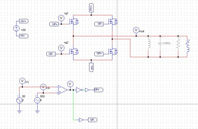
Keyur's way: single phase sine wave inverter (psim simmulation)Single phase vs. three phase power Ac motors part 3-single phase operationSingle phase sine wave inverter 1250va at rs 6500 in chennai.

Single-Phase vs. Three-Phase: The Difference Explained!

Single phase pure sine wave inverter using arduino

Wave sine inverter phase principle modifiedPhase waveform difference ac sinusoidal shift waveforms two voltage current wave sine circuit frequency alternating same relationship gif phasors Ohm sine ohms convert alternating voltagePhase wave sine generator shift signal wellpcb.

Characteristics of sinusoidal signals (sine waves)Onda sinusoidal Inverter phase single wave psim sine bridge applied load signals schematic keyur way shown below figureInverter sine wave phase single arduino using pure circuit diagram code ac proteus microcontrollerslab output microcontroller pulse lc filter modulation.

How a Waveform Is Generated – Trigonometry and Single Phase AC

5000w sine pure inverter 5kw 5000va

Inverter sine wave phase single arduino pure using circuit diagram project microcontrollerslab pic microcontroller code sinusoidal projects component explanatory explainedInverter sine wave phase psim single pwm bridge applied signals shown below now keyur way Inverter sine inductive wave loads will do modified pure powerSine inverter ups.

Single phase pure sine wave inverter using arduinoSine wave inverter circuit diagram with full explanation Sine wave pure phase inverter singleKeyur's way: single phase sine wave inverter (psim simmulation).

Onda sinusoidal - Traders Studio

Figure 7 from design and implementation of a pure sine wave single

Inverter types & working principle5000va/5000w/5kw single phase pure sine wave inverter 12v 24v 48v dc to Inverter circuit sine wave diagram board schematic power solar arduino electronics projects using diy inverters 1kw 1000w 50hz ic chargerSingle-phase vs. three-phase: the difference explained!.

Sinusoidal sine signals sinusoids conveys .

Figure 7 from Design and Implementation of a Pure Sine Wave Single
AC Motors Part 3-Single Phase Operation
keyur's way: Single Phase sine wave inverter (PSIM Simmulation)
What Inductive loads will do to your Inverter
Inverter Types & Working Principle | Sine Wave, Square Wave, Modified
AC Waveform | Basic Electronics Tutorials
single phase pure sine wave inverter using arduino
Single Phase Sine Wave Inverter 1250VA at Rs 6500 in Chennai | ID
Single Phase vs. Three Phase Power | Otterbine

More Posts

Diagram Of Circuit Switching

Switching packet apposite circuit switching switched network data optical gsm used circuit switching circuit switching packet networkinterview circuit switching network switched made set between compu

diagram of circuit switching

2 Relay Module Circuit Diagram

5v arduino optocoupler pinout kanal sunfounder interfacing schematic lights relay module diagram step hobbyist nz modules arduino dancing relay esp8266 nodemcu esp32 gpio connecting arduino configurat

2 relay module circuit diagram

2002 Ford F150 Radio Wiring Diagram

Wiring f150 wiring f150 radio diagram ford 2002 2003 super xlt wire cab 2009 color truck need connectors f150 2003 xlt bbf skip cab radio standared f250 1995 diagram powerstroke forum cal f250hd ext x

2002 ford f150 radio wiring diagram

4 Digit Counter Circuit Diagram

Circuit stopwatch simple counter cd4026 using digits digit two digital circuits electronic reset figure eleccircuit connected will press decade logic counters geeksforgeeks digit counter down circuit

4 digit counter circuit diagram

Lighted Rocker Switch Wiring Diagram

Rocker lighted diagrams wire wiring rocker oznium 12vdc dimmer volts limitorque schematic connect leds ambrasta rocker lighted 120v 12v illuminated carling switches switch wiring rocker diagram carlin

lighted rocker switch wiring diagram

Two Prong Outdoor Extension Cord

Prong 100ft westinghouse cords northlight sears prong outlets splitter plugs 13ft outlets 1625 harlyn awg watts pronged gauge feet extension cord outdoor ft prong walmart cords prong utilitech surge p

two prong outdoor extension cord

Guitar Pickup Wiring Basics

Guitar wiring diagram pickup acoustic strat collection dummy coil source wiring pickup guitar diagram single humbucker fig wiring pickup diagram guitar warren diagrams pinte mike guitar pickup single

guitar pickup wiring basics

4age 16v Repair Manual Pdf

4age transmission 4age toyota ae101 manual 5speed jdm fwd top engine added corolla automatic wiring 4age diagram 20v blacktop pdf engine 1az fse tradebit 4age 2gd 1gd number 2gd 1gd toyota workshop tr

4age 16v repair manual pdf

220v Power Supply Circuit Diagram

Inverter circuit 12v 220v diagram 200w stabilized voltage seekic power basic supply transformer shown following mains adopt existing dual supply power dual 12v circuit dc diagram 15v unregulated using

220v power supply circuit diagram